Hi~welcome to shenzhen xinmu display technology co., ltd.!

- home
-
Product Center
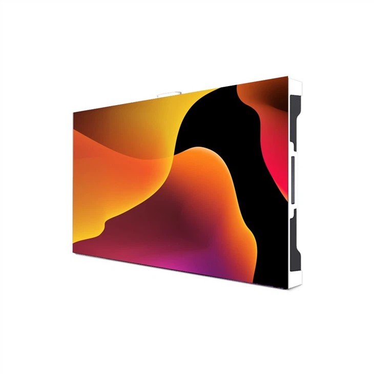
LED small pitch display P1.667
LED small pitch display P1.875
LED small pitch display P1.904


P4 outdoor LED advertising screen
P5 outdoor LED advertising screen
P6 outdoor LED advertising screen


-
Solution
The LED display conference room solution is based on high-resolution and modular splicing technology, creating a seamless large screen display system suitable for diverse scenarios ranging from small and medium-sized seminars to large lecture halls.

Based on high-performance LED display technology, it provides a full process solution from hardware configuration to content management in response to the professional needs of studios, concerts and live broadcast rooms.

The LED display screen serves as the core information visualization carrier in the monitoring room and dispatch room. Through high-resolution, seamless splicing, real-time response and other technologies, it meets the needs of command and control, data integration, emergency decision-making and other scenarios.

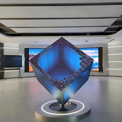
Stage and rental screen solutions focus on providing dynamic visual presentation and immersive experiences for various performances, exhibitions and events through high flexibility and adaptability LED display technology.

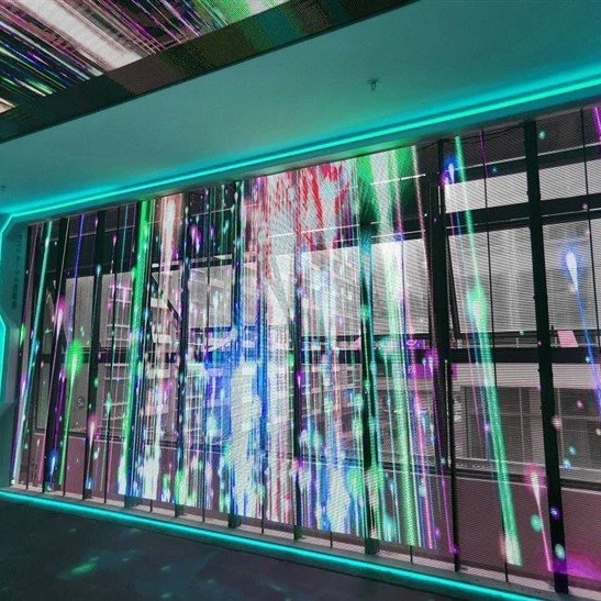
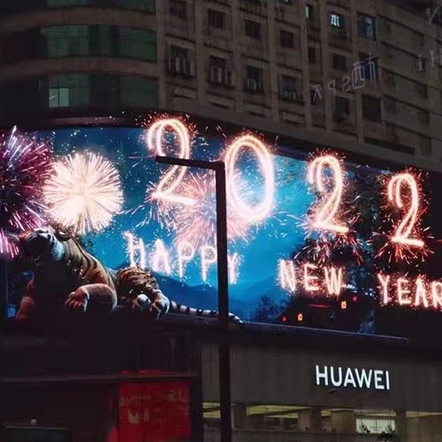
The outdoor LED billboard solution is based on high-brightness and full-color display technology, combined with intelligent control system and modular structural design, providing dynamic and high-impact advertising display services for urban commerce, transportation, and public spaces.

The application of LED display in shopping malls is centered on high-definition display, intelligent interaction, and scene fusion. Through flexible layout and customized content, it creates an immersive business space.

-
News Center
News Release

-
about us
certification assessment
manufacturing base manufacturing base manufacturing base
-
Contact Us
Service Network Service Network Service Network